Greta Varani
Keep working on the Cad file of the previous lesson.
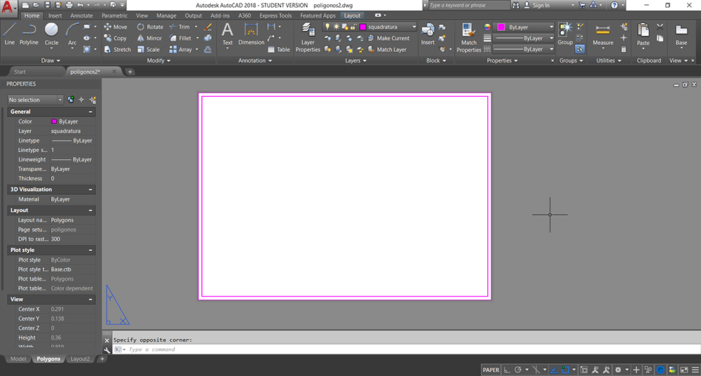
In the layout space, cut the lines that exceed with the command FILLET (radius=0), clicking on two lines that intersect each other. Convert them in polyline with the command PEDIT -> Join, then make an offset of 0.05 of them. Change the thickness of the line with the command PEDIT-> Widt, and digit the new thickness as 0.0005.
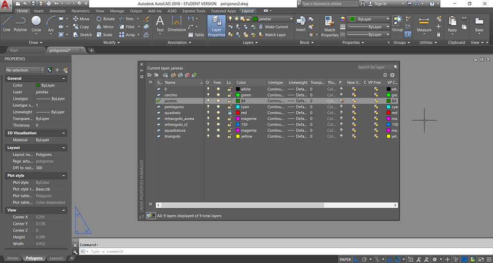
Create two new layers for the squaring and the windows, and make the windows layer not printable.
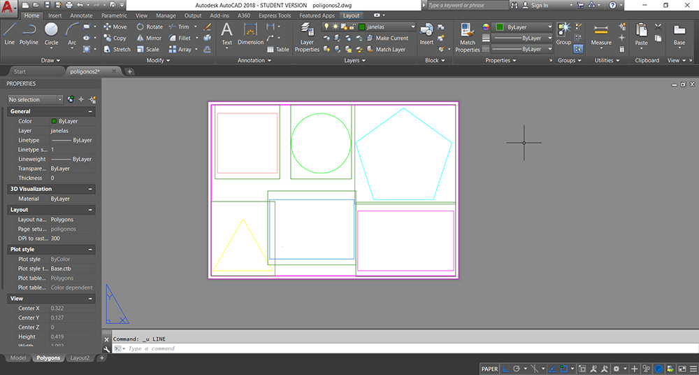
Using the command MVIEW create a new window.
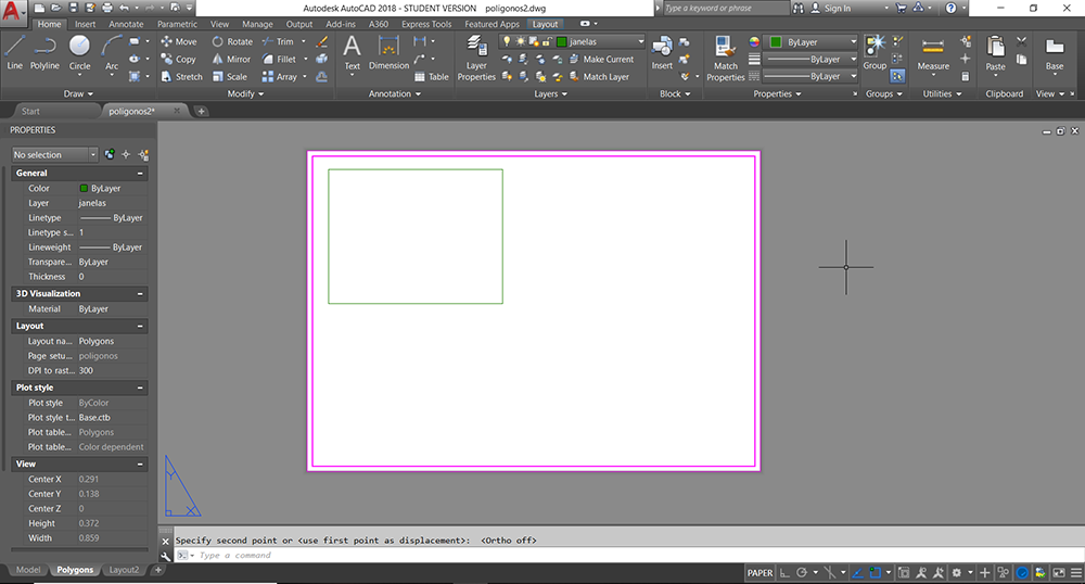
Clicking two times inside the new window, use the command ZOOM and digit 1/10xp for scale the drawing, then center it in the windows.
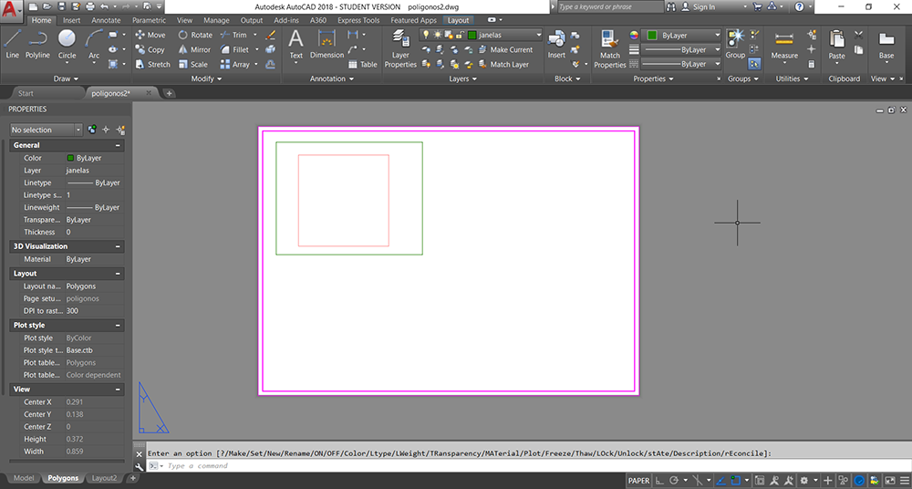
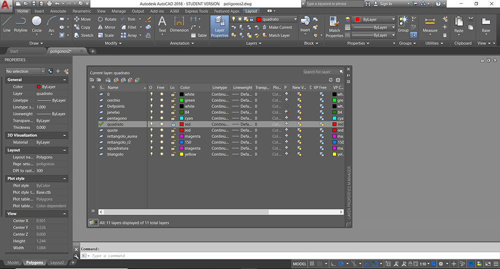
For making appear only the square, open the layer proprieties and freeze all the layer except the square's one in the window.
Returning in the paper space, do the same operations for all the other shapes.
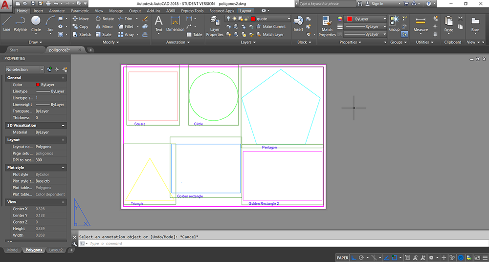
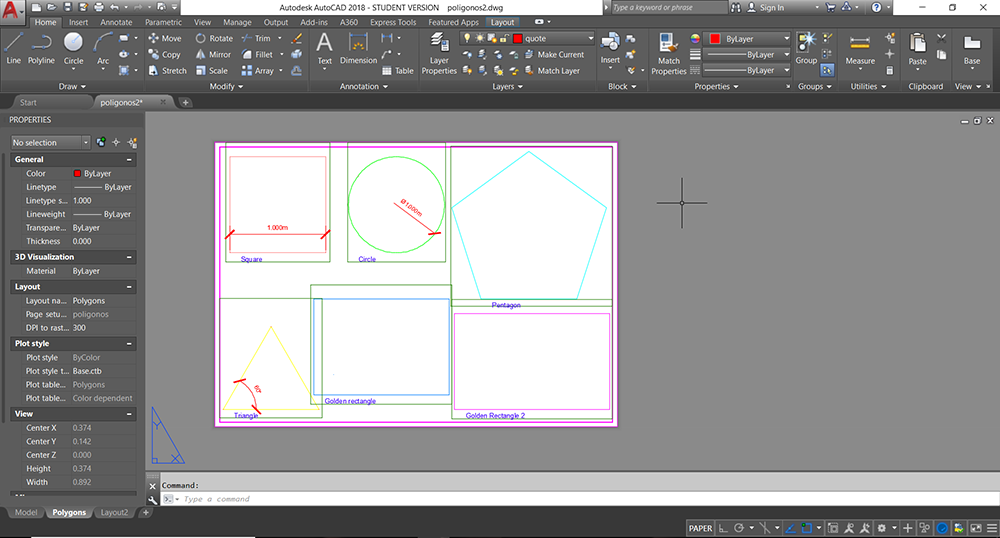
Create then other two layers: Text and Quote. selecting the text layer and working in the paper space, use the command DTEXT ->0.005 -> 0, to create a dynamic text and place it under one of the shape. After writing the name of it, repeat it with all the shapes.
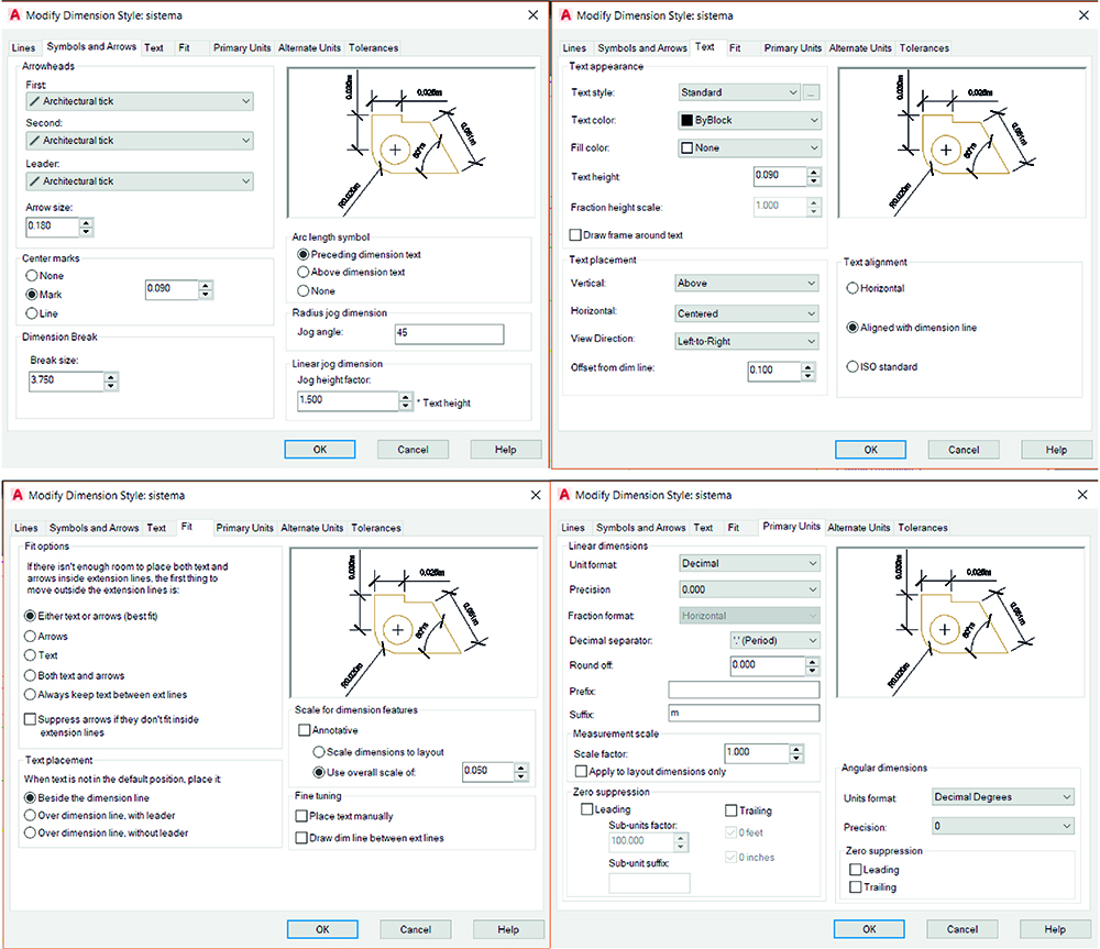
With the command DIM draw the first quote for the late of the square. Select it and in the proprieties select the style "standard". Then, with the command DIMSTYLE change the proprieties of the "standard" style as shown in the figure below.
With the commands DIAM draw the quote of the radious of the circle.
If necessary, expecially in the angular quote, you can delete the suffix "m" just changing it in the proprieties pannel of a selected quote (dim suffix).
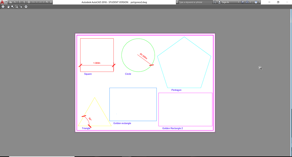
Finnaly, it's possible to see a preview of the print and check if everything is correct.
Sumários